My trusty mallet, Thagomizer, has really been taking a beating in the last year. I think I’ve had to glue it back up about four or five times now. With some extra time on my hands, it was time to build a replacement.
I liked a lot of things about the mallet, but did some silly things when I made it. The handle turns out to be a little too short, and for whatever reason, I put a finish on it. I guess I was on a varnishing kick back then; come to think of it, I really didn’t have anything else to varnish at the time. (I used rottenstone on this? Really?)
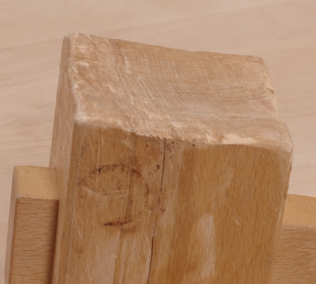
However, what interests me most is the question of if I could make a new one last longer. Everything on the original was very durable, except for the top of the head. It picked up a habit of splitting late in life. My first step was to take a good look at what had happened:
Notice that the face has become concave after repeated pounding. The fractures are all mostly in the top 1/3 of the head. I suspect that what’s going on here is that smacking something (like a holdfast) on the upper part of that concavity put a lot of shear force along the top, and that’s why it did what it did. Back in this post (way back when no one ever read this blog), I explained that I wasn’t going to put a bevel on the top because I was being lazy. So perhaps those bevels aren’t there just for show, and I knew one thing that I needed to do in the new one.
Because I didn’t have any really thick stock at the time, I built the old mallet by face-gluing pieces of wood. That turned out to be pretty durable, so I did the same thing this time, using the same trick to get the hole in the middle, except that I was considerably less meticulous about it:
I used a bunch of scrap wood this time (but from the same board as the old Thagomizer!), and decided that I cared only to (sorta) align the pieces on the bottom of the head because I’d just be chopping off massive pieces anyway. This might look a little stupid, but not nearly as stupid as what I did for the new handle:
I had the perfect piece of scrap, but it was just a tad too narrow, so I glued another piece of scrap to the end to get what I needed (and sawed most of it away in the end).
So I had the head and handle parts glued up, and it was time to shape everything. Here again, I was considerably less meticulous than last time. I sawed most of everything on the head, did the final passes on the top of the head with my jack plane with the deep camber, and chamfered the sides with that plane as well. As far as the handle goes, on the last one, I’d been all enthusiastic about using a spokeshave. Well, that spokeshave enthusiasm doesn’t happen nearly as often to a man who has a Shinto saw rasp in his hand. (Save the spokeshave for more delicate tasks.)
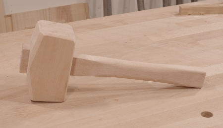
When everything was said and done (in a far less amount of time than the original), I had Thagomizer Jr.:
The top of the head is beveled down, the corners at the top are considerably chamfered, and the handle is a couple of inches longer. The head weighs a little less than the original, but the extra handle length probably brings it to about the same weight, but with a different balance.
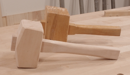
So I’m ready to start beating on stuff now. Here’s a comparison of the original and new one:
Time and use will tell if the alterations do what they’re supposed to do.
One annoying gap in my tool set has been the panel gauge-sized hole. I’ve gotten really frustrated with normal marking gauges from time to time, because they get significantly more difficult to use after you extend the arm more than a couple of inches. It’s not so much a matter of the length of the stock (especially in the case of my gauges), but more of a problem with registration. Keeping the stock at a steady height when you’re worrying about a long arm is a bother. Proper panel gauges include a rabbet to register on the edge of a board or panel when you need such a thing.
I decided to make my gauge out of scrap, and after scrounging around, I found this cherry offcut from the second nightstand project:
It was already 4/4, which was about the thickness that I desired (I’d originally thought about laminating two contrasting species, but decided not to waste my time jointing faces and waiting for glue to dry). After cutting it to length and approximate height, I jointed the bottom edge and cut the all-important rabbet:
In hindsight, it would have been a better idea to cut that rabbet until after I’d mortised the hole for the arm, but it didn’t end up mattering much.
Next I cut the arm’s profile. After my previous experience with arms flopping side-to-side and fixing them, I decided to take a more radical approach to really locking the arm in place. The Lie-Nielsen panel gauge and a version of the Stanley #65 marking gauge rotate the arm 45 degrees so that there is a triangular profile on the bottom of the arm to really lock it into the stock. It’s the same concept as the ol’ “wedge crowds the arm into a corner” trick, and I thought it was worth a shot because people do seem to rave about the design.
So I marked it out a little on the arm that I’d chosen (another piece of scrap cherry), and roughed it out with my jack plane:
When I got close to the lines, I switched to my Veritas low-angle block plane with the chamfer guide attached:
You can see the profile starting to come through at the end.
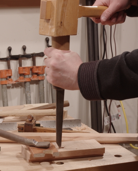
Next, I turned to the mortise. I just banged it out with a pigsticker as usual:
Then it was time to test-fit the arm and to see if this profile really did what it was supposed to do. I slipped a couple of wedges in where the thumbscrew would eventually go, then tried to get the arm to wiggle around:
Much to my delight, it worked. Keep in mind also that I wasn’t even being terribly accurate in chopping the mortise (call it “mostly sorta accurate”).
With everything fit, I shaped the top of the gauge (entirely with a coping saw and Shinto saw rasp), then bored the hole for the machine screw insert with a brace and auger bit:
The brass screw inserts have slots for driving them with a screwdriver, but brass is so malleable that the slots are next to useless. Instead, I use a screw with a nut threaded on to drive them in. In this case, I was using a hex-headed furniture connector to ensure that my driver bit wouldn’t slip:
This works well for driving the insert, but cherry being what it is, there was a little bit of spelching near the top. Yeah, I should have probably driven this thing in before shaping, but whatever–I just filed off that layer.
(Here, I must again remark that I would love to use wooden screws and threads for this. It would work wonderfully.)
To finish off the stock, I made a “saddle” for the thumbscrew and arm as described back in this post.
Now it was time to turn to putting the blade in the arm. I used a Millers Falls #5 to drill a couple of holes in a line at the end to make the mortise for the blade:
That miniature square I got in Japan really comes in handy.
To hold the blade in place, I used a smaller screw insert in the end (who knows how well this will hold up) and a stainless steel cap screw to go in the front. I made a saddle for this as well.
The blade itself is yet another small strip of spring steel. I’ll be honest here–I don’t particularly like using spring steel for this because it does not hold an edge as well as tool steel. However, it’s such a pain in the butt to sharpen the blades that I figure I’ll keep using spring steel until I can come up with some sort of honing guide for the marking gauge blades.
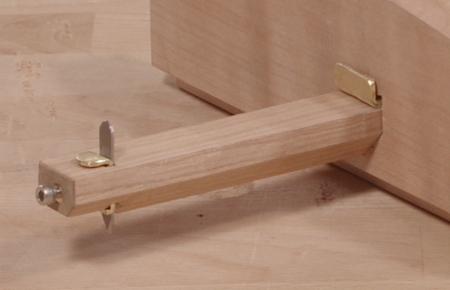
And that was pretty much it; the process only took a couple of hours. Here’s the finished product:
And a close-up of the business end, showing the cap screw and various “saddles:”
With all of that said, the important question is, “how well does it work?” I had to admit that I was a little bit doubtful on how much of an improvement the arrangement with that triangular/inverted-house-shaped mortise and arm profile would bring. It turns out, though, that it’s really something. The arm simply does not budge when you tighten the thumbscrew. It’s so impressive that I may do a retrofit on my previous marking gauge.
I’m still unsure about the blade-holding mechanism, though. I just hope that it doesn’t split the end of the arm.
It’s time to get down to that new workbench. Everyone and their uncle is building a Roubo this year. Consequently, I’ll just be another voice in the din of people blogging about their Roubo builds, but hey, I’ll have a new workbench at the end.
I got the first pieces of wood for this project late last year. A fellow BAG has a pretty serious quantity of reclaimed douglas-fir sitting around and was gracious enough to offer it my way (thanks Bill!). This is big stuff–basically 4x12s and 4x14s supposedly taken from a warehouse. Reclaimed douglas-fir has many advantages, but two of the biggest are that it’s quite hard (yet easy to plane), and it’s really, really stable.
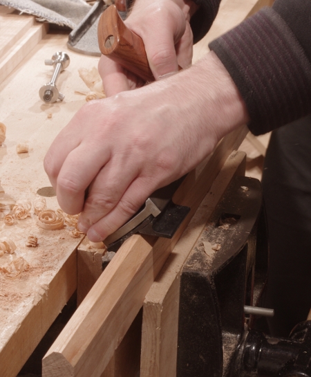
The boardstimbers had a layer of cruft on the faces, consisting of oxidization, dirt, and who-knows-what. After cutting roughly to length, I sawed off the crud. That process looked like this:
I’ve decided that I will do this project completely by hand, just so that I can say that I didn’t wimp out with a bandsaw (or something of that sort of masochistic nature). Freakishly-looking disembodied arm aside, I’ve been doing all of the heavy-duty ripping like this, and it’s really not that bad (Remember how I mentioned that reclaimed douglas-fir is really stable? That helps). The timber is held steady by the front vise of my current bench.
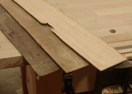
Getting rid of the grime this way yields funny cruft veneer:
I could probably sell this stuff to an artist.
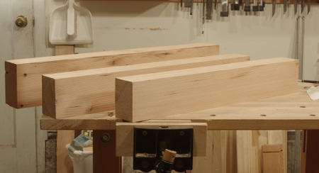
So after sawing, I finished sizing up everything with the usual cast of planes. With the wood I had on hand, I got three major components of the base: two legs (front and middle) and a stretcher (rear):
The plan for the legs is 5″x3.5″ and the stretchers will be 6″x3.5″. I won’t be thicknessing the stretchers precisely because there’s no need. You can tell how the scale compares to my current bench from the preceding photo.
And now I’m out of wood, at least for big stuff. Time to get another load!
[edit: It planes easily, but as I learned later, this wood dulls plane blades very quickly.]
When it dawned on me that I needed a workbench, I really didn’t know my requirements. The only thing that I knew for sure is that it had to be really strong, pretty heavy, and be able to resist racking forces. I hadn’t studied workholding all that well, but there is so much conflicting information on this subject that it probably wouldn’t have helped.
Now that I’ve used the bench that I made for about four years (and read about many other kinds of benches), I have a much clearer picture, and, well, it’s time to evaluate how I did. Since this post falls under the “goofs” series, you probably have an idea of how this is going to go.
However, let’s start with something that really worked for me: the base.
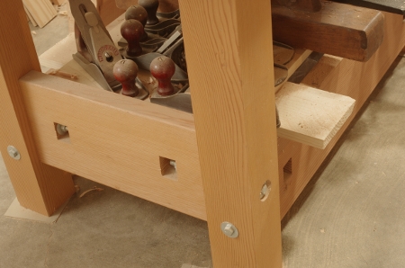
It’s a very simple knockdown design secured with bolts and captured nuts out of douglas-fir. In general, bigger is better when building the base. I used lone 2x4s for the legs on my first build, and despite looking a little flimsy in the front-to-back direction, it still worked fine. One of the reasons is that I used big 2x8s as stretchers in the front and back. That created so much surface area that a simple butt joint secured with the bolt meant that it never, ever racked side-to-side.
However, it was still a little on the light side for what I wanted, so when I moved out of the apartment and to my first shop, I replaced the legs with 4x4s and the side stretchers with 2x8s.
That change removed any doubts I had about this design. The Schwarz slightly poo-poos knockdown construction, complaining that you have to tighten up the bolts from time to time. I have not run into this as an actual problem. It’s just not that hard of a thing to do, and it’s not like it happens all of the time, either, especially when your wood is reasonably dry and stable (think douglas-fir), and you have an enormous joint mating area. I may have done it twice during the whole time I’ve used my bench.
With the added mass, I didn’t have a problem with the bench moving around as I used it in the old shop. I do have that problem when using the frame saw in the new shop, however (but not when planing or anything else). It’s primarily because the polished concrete floor is significantly slippery. I need to put down some really grippy rubber feet to fix this (or something of that nature).
I also put an improvised shelf in almost immediately–just a piece of plywood suspended over two boards. I put my larger bench planes there. It’s a great feature to have on a bench.
The top I used was a mixed bag of results. On one hand, it’s thick enough to take a pounding and it’s reasonably heavy. On the other hand, it really didn’t want to stay flat, it still could have been a little thicker, and it’s too deep. Let’s look at these one-by-one.
When I bought the top (an Ikea countertop made from beech), it was quite flat, but it started sagging at some point. I don’t know when that was, but it was pretty severe by the time I decided to flatten it. If I’d been paying attention, I would have flattened it earlier. It seems to be OK now, though. Sure, you have to flatten all workbench tops, but I have a feeling that something a little thicker wouldn’t have moved so much (unless it was a solid hardwood slab).
Yes, thicker would have been better. Being beech, the top was fine for taking a pounding as long as you were working near a leg (and that’s what you’re supposed to do anyway). However, a thickness of not even two inches has two weaknesses. The first is that it’s not as heavy as it could be. That’s not such a big deal, but the second issue is that it was difficult to mount the front vise. The model I have really wants something thick, and if you don’t have that, you have to improvise. I did so in an odd way; I’ll talk about that in a bit. But let’s not forget about the lack of dog holes in the front–I couldn’t put any in at that thickness.
The final problem with the top is that it’s too deep. That wasn’t a problem at my old shop, with the bench flush against the wall, but it’s no longer in that configuration, and I have a lot less room to walk around now. And stuff accumulates at the rear of the bench. Given the shop’s current transitional state of tool storage, there’s not much I can do about that, except that if I didn’t have that space, I’d actually be forced to resolve the tool storage issue and not have this problem in the first place.
Now, let’s talk about the junction between the top and base. Much has been written about the advantages of aligning the top and base along the front of the bench, and they aren’t lies. I should have done this and it’s still an option. Were I to do this, I’d need to bring my front vise chops into alignment as well (see below). One thing I’ll say about the top overhang is that I wonder why I put in an overhang of a half-inch at the rear of the bench.
Yeah, that’s just weird.
The top is attached to the base with flimsy L-bracket-style hardware. Strangely enough, it works. The top is so heavy that even with the most measly of lag screws holding things together, it never moves. It doesn’t vibrate. This still surprises me, given what the benchtop has to endure. Were I doing this over again, I’d probably do mortises just to keep it aligned (it’s a pain to put the top back on when you move from place to place), but I wouldn’t do Schwarz-style through mortises. They just don’t need to be that deep. However, it should be secured in some way just to keep the top from jumping around.
Keep in mind that this particular junction matters a lot more if you’ve got a leg vise. With a leg vise, you’re typically applying (very strong) pressure from the legs to the top, so something flimsy like my current setup wouldn’t work. However, if you’re using a front vise, that’s mounted on the top alone, so it doesn’t matter as much. I have my own ideas for the ideal joint in this situation, but they are just ideas at the moment.
So, speaking of workholding, I learned a lot about it from this bench. Before I even installed the front vise, I used a Veritas Wonder Dog, homemade bench dogs, clamps, and a handscrew to get things done. I still haven’t installed a tail vise-like thing (see below). You don’t need too many dog holes, and I prefer the round ones because they’re just more flexible.
You don’t need an end vise, but they are faster to move into position. If you decide not to do an end vise, you should probably put a couple more intermediate dog holes at the end, and bore a second set of aligned holes so that you have two points of pressure for the double-wedge method. You will use this method eventually, even if you have a wonder dog, because the wonder dog is hard to use with thinner boards.
And then there’s the matter of the front vise and the overhang.
My install of the front vise is, to say the least, one of the stranger features of the bench. Due to the way that the Jorgensen front vises are designed, you secure it through the front and underneath (other manufacturers have you do it all from the bottom). And here’s where the thickness of the bench got to be an issue again. The vise wants a certain thickness that I don’t have, so I ended up shimming the bottom and the front of the vise. The result looks strange, and in use, it’s got some “special” working qualities. If I were doing this again, I would glue a thick strip of hardwood or douglas-fir to the front of the bench as an apron-like thing, inset the vise into that, get everything flush to the front of the bench, and be done with it.
The major issue is the overhang. Much has been written about the advantages of having the top flush with the front legs, so I won’t bother with repeating that here. But another disadvantage is that if you have a front vise sticking out with so much overhang like this, if you put something really heavy in there, the bench gets to be a bit front-heavy. It’s not enough to have it tip over, but it is enough to get the rear legs to very slightly lift up when you’re doing a heavy sawcut (not coincidentally, the most likely thing you’re going to do when clamping something very heavy).
Despite the strangeness, the front vise does a pretty good job, about as well as you can expect for a vise of this design. The quick-release design is polarizing. On one hand, it’s very fast. A half-turn back and it releases. On the other hand, you can’t use the vise for spreading operations, as you would be able to on a model with the little release trigger. One common complaint about these types is that the guide bars make it difficult to secure boards vertically (for dovetailing, for example). The good news is that the guide bars of this model are well-made, so the racking is kept to a minimum. I hardly ever need to use spacers to even things out.
An advantage by accident is that having the vise protrude so much allows you to get behind the cut when you’re sawing tenons.
So that’s the bench evaluation–that’s what I’ve learned from this one. There are lots of things I could do to improve this bench, but I won’t. Why?
Because I’ve got the green light to make a new bench. And I’ve already started.
For the last month, I’ve felt so close to finishing the twin-nightstand project that I thought it could all come together at any moment. The final details proved as time-consuming to complete as the rest of the thing.
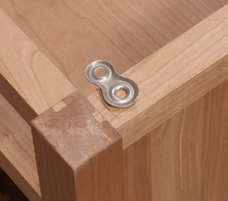
I’ve been varnishing for maybe a month. When I’d gotten enough onto the cabinets, I took care of two remaining steps before the final rubout. The first was how to attach the tops. I decided to use figure 8 connectors because they seemed like a pretty neat approach. Placing them into the cabinets was relatively easy. First, I marked out a box (with no particular offset):
Then I chiseled mostly down to the depth of the connector, using my Veritas mini router plane to go to the bottom:
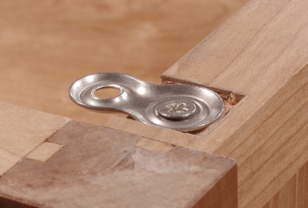
Then I predrilled a screw hole and did a test fit:
Marking and predrilling the corresponding holes in the tops was a fairly simple matter. However, attaching the tops was more difficult due to the limited space between the shelf and the top. I used a stubby screwdriver, a socket wrench with a driver bit, and practically no vision whatsoever.
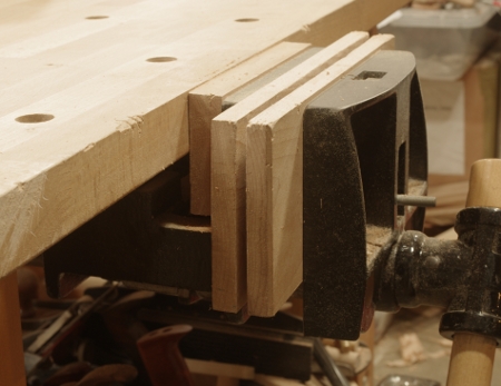
The other final task not related to finishing was to cut the legs to height. I didn’t cut the legs to length at the start because I knew there would be some adjusting to do at the end. However, I couldn’t use the ol’ “put the legs under shims, put on a level, flat surface, and mark around” method that’s become popular, because I wasn’t doing a single piece–the nightstands were identical and had to be the same height.
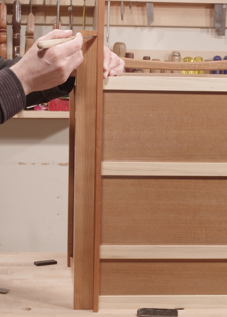
It was easy enough, though. I took a long, thin piece of scrap, marked the desired height to that, then flipped the pieces upside-down (without the tops) on the bench, and marked to that:
It’s a little difficult to see the scrap here because it’s also a piece of cherry, but it’s the thin thing sitting up next to the foreground leg. After making the mark, I scribed around from that mark and sawed off the ends. It worked fine.
Varnishing and sanding between coats was the main time-consumer in the final stages. The cabinets and the drawers got four coats and the tops got five coats. As I have done with the last few projects, I rubbed out the finish with a progression of lubricated #000 and #0000 steel wool only. This was a matte finish again, so I didn’t feel the need to use rottenstone. And really, #0000 does leave a very good finish if you follow the grain most of the time.
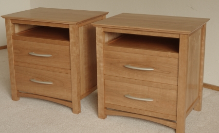
So here are the two together:
If you look closely, you’ll see that the drawer fronts are carefully arranged for continuity left-to-right as well as a balanced figure. On the left piece, the fronts have “cathedral grain” in the same orientation, and on the right, they have ellipses, also in the same orientation. But it turns out that the board used for these fronts was cut so that the front on the top left was next to the front on the top right, and the same is true for the bottom drawer fronts, so there’s a bit of continuity when you look at them left-to-right. (In the end, this probably doesn’t matter at all because they’re not going to be placed terribly close to one another and no one would notice, so don’t think of this as a sort of profound design choice.)
The handles are “halo” handles from Lee Valley.
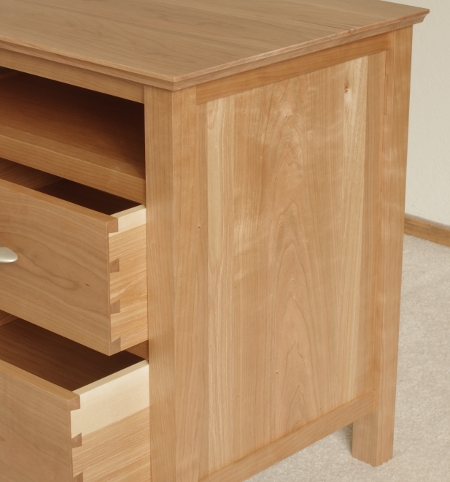
A closeup of the right-hand cabinet and drawers:
I need to make a note about what’s going on with the woods here. In the side panel, there is a roughly 6″ wide slice of flatsawn cherry stock in the center to give it the central cathedral figure; each side panel has this. On each side of that, there are narrower strips of birch meant to provide contrast as stripes. Then, the outermost strips from the center of the panels are again cherry.
This didn’t quite work out the way I’d planned. I wanted to birch to be slightly brighter and contrast just a little more so that you could see what was going on. It was supposed to be subtle, but not this subtle. However, the grain selection worked, so I’ll take that one.
And then there’s the drawer side fiasco. I said this before, but I’ll say it again: Use something reasonable for drawer sides, not yellow birch. The sides did turn out to look interesting enough, but these were such a nightmare to thickness, surface, and cut tails into that I really don’t recommend that anyone ever do it. Yellow-poplar is a great secondary wood and I should have used that.
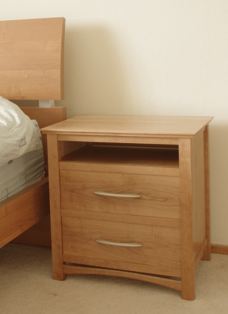
But what’s done is done, and none of this is terribly important in the end. What is important is that they are in use now, and the final placement looks like this:
There’s something very important to note here–These pieces do not incorporate as graceful of a design as my first nightstand. They don’t have the elegant, long legs, they don’t have the simple square footprint, and they don’t have the fancy double-arc decoration. Furthermore, they took longer to build because there are more innards.
So is it a step back from a year and a half ago? It would be if form were everything. But these were designed primarily for function, with the form fitting into a context–they flank a somewhat cheap bed that has no particularly graceful features of its own. They are a tad fancier than the bed itself. Eventually, I will build a replacement for the bed, and at that point, I can make the bed do what the nightstands cannot do on their own.
(The function should speak for itself–I had strict instructions to incorporate a large top surface, plenty of deep drawers, and easily-accessible shelves.)
And there’s one more final step forward with these pieces. I kept them in the same room as the first nightstand while I waited for any remaining solvents to evaporate, so I was able to compare them. The craftsmanship is definitely a step up from back then.
As a postscript, I again need to thank Kirk Eppler, who helped out in a couple of ways when I was building these things.