One annoying gap in my tool set has been the panel gauge-sized hole. I’ve gotten really frustrated with normal marking gauges from time to time, because they get significantly more difficult to use after you extend the arm more than a couple of inches. It’s not so much a matter of the length of the stock (especially in the case of my gauges), but more of a problem with registration. Keeping the stock at a steady height when you’re worrying about a long arm is a bother. Proper panel gauges include a rabbet to register on the edge of a board or panel when you need such a thing.
I decided to make my gauge out of scrap, and after scrounging around, I found this cherry offcut from the second nightstand project:

It was already 4/4, which was about the thickness that I desired (I’d originally thought about laminating two contrasting species, but decided not to waste my time jointing faces and waiting for glue to dry). After cutting it to length and approximate height, I jointed the bottom edge and cut the all-important rabbet:

In hindsight, it would have been a better idea to cut that rabbet until after I’d mortised the hole for the arm, but it didn’t end up mattering much.
Next I cut the arm’s profile. After my previous experience with arms flopping side-to-side and fixing them, I decided to take a more radical approach to really locking the arm in place. The Lie-Nielsen panel gauge and a version of the Stanley #65 marking gauge rotate the arm 45 degrees so that there is a triangular profile on the bottom of the arm to really lock it into the stock. It’s the same concept as the ol’ “wedge crowds the arm into a corner” trick, and I thought it was worth a shot because people do seem to rave about the design.
So I marked it out a little on the arm that I’d chosen (another piece of scrap cherry), and roughed it out with my jack plane:

When I got close to the lines, I switched to my Veritas low-angle block plane with the chamfer guide attached:
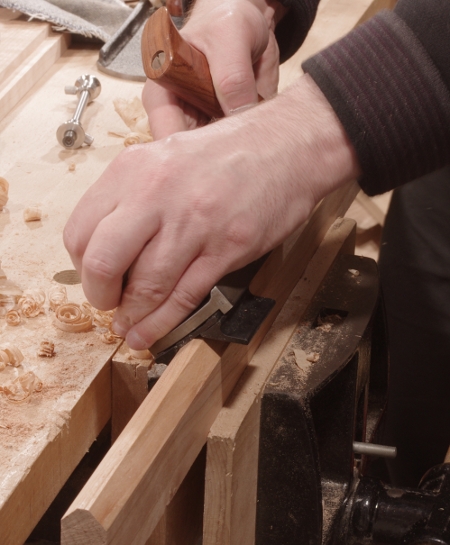
You can see the profile starting to come through at the end.
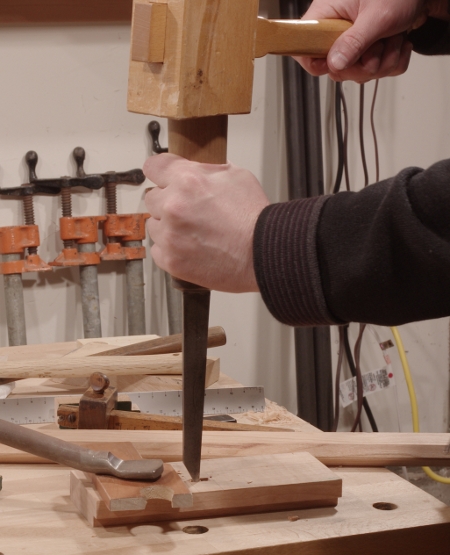
Next, I turned to the mortise. I just banged it out with a pigsticker as usual:
Then it was time to test-fit the arm and to see if this profile really did what it was supposed to do. I slipped a couple of wedges in where the thumbscrew would eventually go, then tried to get the arm to wiggle around:

Much to my delight, it worked. Keep in mind also that I wasn’t even being terribly accurate in chopping the mortise (call it “mostly sorta accurate”).
With everything fit, I shaped the top of the gauge (entirely with a coping saw and Shinto saw rasp), then bored the hole for the machine screw insert with a brace and auger bit:

The brass screw inserts have slots for driving them with a screwdriver, but brass is so malleable that the slots are next to useless. Instead, I use a screw with a nut threaded on to drive them in. In this case, I was using a hex-headed furniture connector to ensure that my driver bit wouldn’t slip:

This works well for driving the insert, but cherry being what it is, there was a little bit of spelching near the top. Yeah, I should have probably driven this thing in before shaping, but whatever–I just filed off that layer.
(Here, I must again remark that I would love to use wooden screws and threads for this. It would work wonderfully.)
To finish off the stock, I made a “saddle” for the thumbscrew and arm as described back in this post.
Now it was time to turn to putting the blade in the arm. I used a Millers Falls #5 to drill a couple of holes in a line at the end to make the mortise for the blade:

That miniature square I got in Japan really comes in handy.
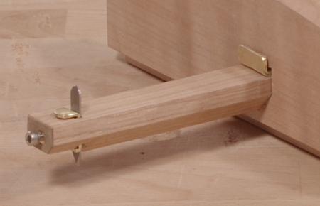
To hold the blade in place, I used a smaller screw insert in the end (who knows how well this will hold up) and a stainless steel cap screw to go in the front. I made a saddle for this as well.
The blade itself is yet another small strip of spring steel. I’ll be honest here–I don’t particularly like using spring steel for this because it does not hold an edge as well as tool steel. However, it’s such a pain in the butt to sharpen the blades that I figure I’ll keep using spring steel until I can come up with some sort of honing guide for the marking gauge blades.
And that was pretty much it; the process only took a couple of hours. Here’s the finished product:

And a close-up of the business end, showing the cap screw and various “saddles:”
With all of that said, the important question is, “how well does it work?” I had to admit that I was a little bit doubtful on how much of an improvement the arrangement with that triangular/inverted-house-shaped mortise and arm profile would bring. It turns out, though, that it’s really something. The arm simply does not budge when you tighten the thumbscrew. It’s so impressive that I may do a retrofit on my previous marking gauge.
I’m still unsure about the blade-holding mechanism, though. I just hope that it doesn’t split the end of the arm.

I’ve had a problem in searching for a good piece of steel to make a slicing knife for a marking gauge. The simple answer is to use the blade from a used putty knife. It is very hard steel. Better yet, find a putty knife that the blade has some flex, therefore spring steel. This is thin and very hard and makes a great cutting knife.
LikeLike
That’s a pretty good idea, I’ll have to make a note of that one. I’ve toyed around with the idea of making new knives from time to time, but haven’t had the chance yet, as it would be part of a larger project to improve my gauges. Though at the moment, I’m leaning towards trying to do a little forge-welding and heat treating. (I know some people who have been, eh, “bad influences.”)
LikeLike