The vise installations meant that the bench was nearly complete. I did some other minor preparation, such as plowing the grooves for the (as of yet nonexistant) sliding deadman and sawing the legs to length, and then I was ready to assemble. I’d never actually assembled the bench, and for a while, I wasn’t really sure how I’d do it. Thinking about it made my arms hurt.
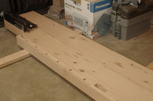
Thankfully, I came to my senses at some point, and when I was ready, I set out two 2x4s to support the benchtop. With the help of SWMBO, I put the top upside-down on these boards:
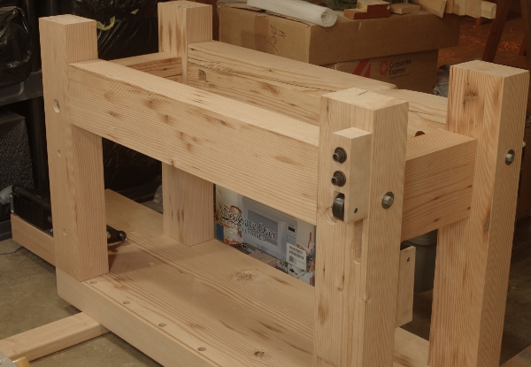
Then I was able to put all of the legs and stretchers in for the first time. Everything fit perfectly:
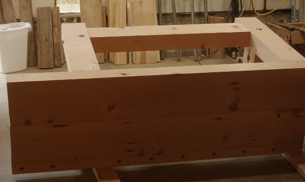
Getting the bench right-side-up simply involved turning the bench on its side (there’s another board underneath the leg here to protect the roller bracket):
And one final lift to get it on its legs for the first time.
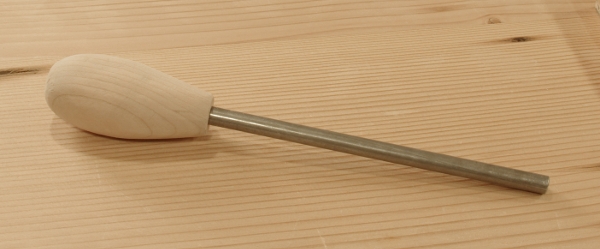
Next, I installed and fine-tuned the chops of the leg and tail vises. The description of that is in those preceding posts (meaning that, yes, I was done with this business before I posted those). It was fun to use the new bench for finishing itself! However, there was one little minor vise item that I hadn’t done, and that was to make a handle for the parallel guide pin. I’d considered making this completely spartan (basically, just a block of wood with the pin in it), but then I noticed that I had just enough wood in what remained of the piece of cherry that I’d used for the roller brackets, and made a really quick-and-dirty handle with my saw rasp:
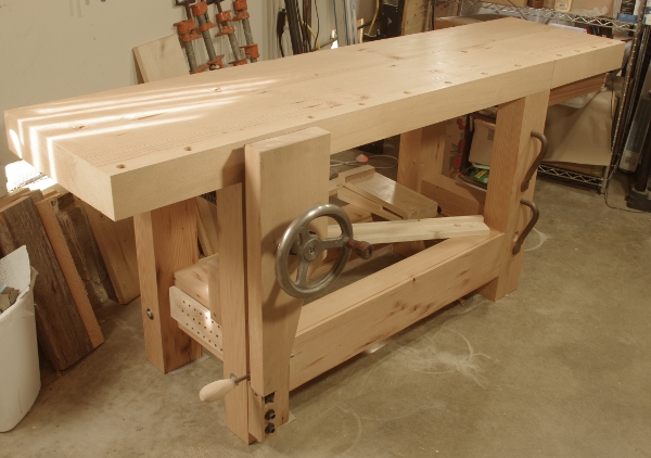
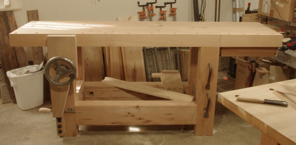
Finally, I sawed off the uneven ends of the bench and it was done:
The front view, somewhat encumbered by the lack of space in the shop:
There are a few minor things left to do, such as the sliding deadman, the shelf, and maybe a tool rack. I can do those at my leisure.
Thanks again to Bill K. (who supplied the douglas-fir) and everyone else who helped me with this. Now it’s time to get back to making furniture.
Right on the heels of the leg vise installation, I did the tail vise. I’ve never had a tail vise, but I’ve always wanted one. As it turns out, AJCP&R got me the Veritas quick-release version about two years ago (thanks again!), but it had to sit in its box for all of this time, waiting for this new bench to be made. That day finally arrived.
There’s been a bit written about the Veritas vise, but what I don’t see much out there about how versatile it is if you’re willing to play around with the shape of the chop. For example, although it’s designed to be used in conjunction with a wide front apron, that’s not necessary. In addition, you don’t need a whole 17″ of free space for overhang on the end. I broke both of these rules in my installation and I got away with it.
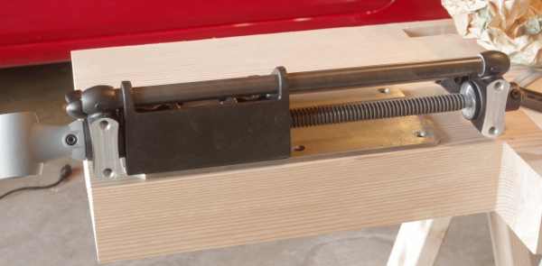
For those who have never seen the vise hardware, it consists of a the vise itself and a mounting plate that you attach to the bottom of your bench. The mounting plate provides the accuracy you need to keep the vise chop just far enough away from the edge of your bench to slide freely. You’re supposed to place the plate 1/4″ from the chop edge, all the way at the end of the bench. I didn’t do that. I discovered that you can get away with moving it about two inches away from the end of the bench, as long as you don’t obstruct the holes for mounting the chop (and you could even do that a little, if you’re willing to give up a bit of the vise’s travel):
The 1/4″ on the front side, however, is a (mostly) hard and fast rule. Here’s how the vise looks aligned on the mounting plate:
Notice that some of the vise hardware slips underneath the end of the bench. Also, some of the hardware on the other side (near where the leg will go, on the right side of this photo) protrudes in that area. I was able to do this because I decided to make the chop deep enough so that this little bit of hardware could slip behind the leg. You could do even more by widening the chop a bit more, but I personally wouldn’t recommend more than four inches because otherwise, you might put the hardware in the way of holdfast holes or something. As long as you don’t have anything silly up there such as a top stretcher between your bench legs, you should be fine.
OK, so the hardware fits. The next rule to break was the wide front apron. Because I designed this for a deep chop, I was able to make the inside of the chop wide (for the mounting screws), but the outside (the part that goes along the front of the bench) would be just the same 3.5″ beech that I used on the rest of the bench. Here’s a view of the chop upside down:
Oopsie on the blowout for the washer holes at the edges, but it hardly matters. At this point in the bench build, I was starting to starve for wood–I had very little douglas-fir of substantial size left. So for the backing piece, I milled and glued up two smaller pieces, and then glued those to the beech.
When it was upright and finished, it looked like this:
I had sort of a hard time trying to decide where to put the dog holes. In the end, I actually followed Lee Valley’s instructions and put the centers 1″ from the front of the bench. I could put in another row if necessary, but somehow I doubt it will be.
This vise really was a snap to install. You have to be quite careful when installing the mounting plate, but it took me longer to the make the chop with all of the milling and glue.
With the large frame components done, I could now work on the bench’s vises. Like everyone else in the known universe, I got a Benchcrafted Glide leg vise for the front (thanks SWMBO!).
The installation is not what I’d call easy, but it’s not ridiculously difficult, either. The first step was to put the holes in the chop (a big chunk of beech I found in the pile), and the leg.
For the chop, you’re supposed to put a shallow hole for a washer around the screw clearance hole–a 1.75″-diameter hole. The only thing I had in that size was an expansion bit. Now, those bits are not known to be terribly good even in soft woods, much less something like beech, but thankfully, this thing needed be just 3/16″ deep, so I used it mainly for the cutting spurs to get the circle.
Now, the main screw clearance holes in the chop and the leg are supposed to be 1.5″ wide, and I didn’t happen to have a No. 24 bit, either. I was all ready to wimp out and turn to the dark side, and in fact, I’d brought the chop and the leg to my friend Jasen’s place to make use of his drill press and Forstner bit. However, while preparing, I poked through his box of auger bits and found a No. 24 Irwin solid-core bit. Arrangements were made to abscond with the bit, and so mad props to Jasen for letting me do so!
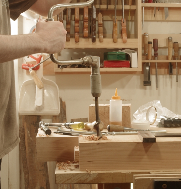
I used my 14″ sweep monster (a Millers Falls #730). For those of you who have never seen a bit this large, consider the following: The brace’s chuck was just barely able to hold the bit, and only because they tapered the shaft thinner near the end.
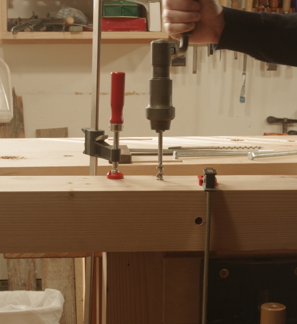
This is the type of job that you have to break out the squares to keep the bore straight:
This is a big job, and it was no small amount of effort to turn the brace. The most difficult part of it, however, was to keep everything straight while exerting enough force.
Once the hole was through, I knocked out the waste in the outer washer hole–my Veritas mini router plane struck again:
So, when everything was said and done, I had two holes: one fancy, one not-so-fancy, both big:
After this, it was off to mark, drill, and tap the holes to attach the handwheel and screw to the chop. This is a particularly tricky job–you really need accurately lay out and drill those holes. (Thank goodness for auger bits.)
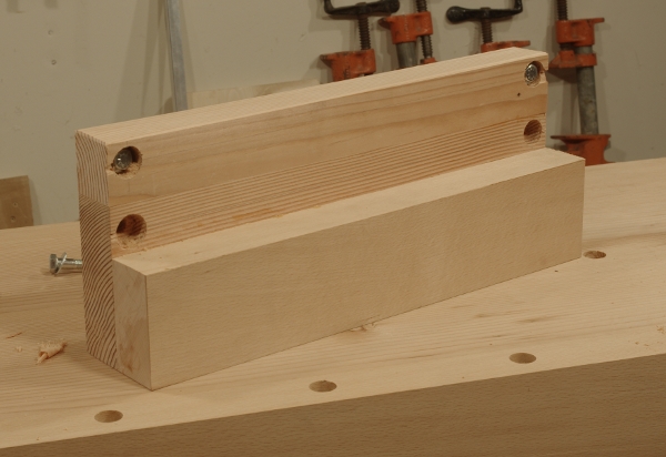
Now, a suspicious reader may have examined some of the photos above and noticed that I was using a peculiar piece of sacrificial wood underneath the chop for blowout prevention and lead-screw continuity:
This might qualify as the dumbest use of cherry in history, but notice the check (actually, compound checks) in the center. This precluded me from making a saw handle or something nice with it, but after I finished wrecking the center, I sawed off the usable wood on the sides for the Glide vise’s roller brackets:
This is sort of more silly luck than clever, I’d think–this offcut was the only thing I had around that wouldn’t require sawing up another board just for a couple of 6″ blocks.
I should also mention that with this bench, I am not trying to use a bunch of different woods to make it a showcase piece–I just want the thing to work. So, having now used three woods (the other two being douglas-fir and beech), I figured I’d use whatever I could find for the parallel guide, and I found none other than the last offcut of that nasty birch that I used as a secondary drawer wood on the second nightstand project.
Another thing that you may have noticed is that the hole in the leg isn’t horizontally centered. This is where I might eventually look like a goat, but I decided to try something a little different with this vise. Looking at the design of a leg vise and the diagonal one that Schwarz used in the “English Workbench” in his first workbench book, it dawned on me that the spot with the highest and most stable gripping power on a leg vise is directly opposite the parallel guide. On most of them, that’s in the center of the chop at the top, but that’s not where you would clamp a number of workpieces because the vise screw is in the way.
But on the diagonal vise, you don’t have that problem. So for better or for worse, I decided to put the parallel guide off to one side of the chop, and in doing so, move the “grip sweet spot” (or whatever you want to call it) off-center at the top of the chop, so that it wouldn’t be right above the screw. Here’s a shot showing the mortise for the parallel guide and a dowel leading to where that spot will be on my bench:
The off-center hole in the leg is part of the design. The idea is to place the spot with the maximum force somewhere around the area where the side of the leg meets the top.
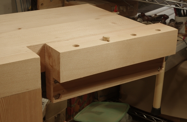
In addition, by moving the parallel guide over to the side, I could move the guide’s clearance mortise in the leg over to the side. There, the parallel guide would slip neatly alongside the giant lower side stretcher rather than above or below, sidestepping one of the common issues when installing a leg vise.
It’s easiest to show this in the nearly finished installation:
Now, at this point, I should mention that more often than not, when you try to get clever, you end up shooting yourself in the foot (especially if you’ve never done this before). To put it lightly, this configuration does not come without difficulty. In addition to having to be extra careful with your layout, you’re also introduction an element of imbalance to a vise that really seems to have been designed to be horizontally symmetric. It goes without saying that when you go tinkering, the chop will want to lean in one direction, possibly binding the vise screw and sliding the parallel guide up against its clearance mortise.
To my surprise, it’s been working well so far. It took some fine-tuning, but the the parallel guide rollers, when set just so, seem to do a good job at supporting a good deal of the weight of the chop. The acetal bushing that comes with the Glide is also instrumental in keeping the chop inline. As an extra measure, I reduced the weight of the chop a bit by sawing off a bit of the lower right, but this may have just as well been to be able to use the offcut for something else.
I still might get burned by all of this, so let’s see what happens. I’m really due with this project–I also lucked out with the length of the vise screw and parallel guide. When vise is closed, they are about 1/8″ from hitting the inside of the rear left leg of the bench.
Now at this point, I have to make a confession: I used a power tool in the vise construction. It’s not what you might think, though. You see, the Glide vise requires you to tap threads in wood. Miraculously, I somehow already had the four taps required for the job (picked them up at a garage sale once but never used them), and I had everything I needed to drill the initial holes for all of the taps by hand. However, what I didn’t have was a tap wrench with a collet large enough to hold the two largest taps. At that point, I had to either buy another tap wrench or think of something else. The taps fit in a brace chuck, but the action on a brace can be a little bit too wobbly for this job. I decided that I didn’t have the stomach to go out and buy some (likely crummy) tap wrench for just this time, so I’d actually follow the instructions for the Glide for a change. I chucked the two big taps into my cordless power drill and threaded the holes with the dark side of the force.
With the legs made, it was time to move on to the stretchers. The method I used was a combination of knockdown and mortise-and-tenon joints. I first made the joints with very short tenons. These are primarily for quick alignment of the joint during assembly.
Then I bored holes square into the legs and had them come out right in the center of where the mortises were. (In reality, I did this before making the joints, but you get the idea.)
The idea is to slip a bolt into the hole and into a captured nut in the stretcher.
The trickiest step was to bore precisely into the endgrain of the tenon pieces. To do this, I assembled the joint, secured it with clamps, then went through the existing hole down into the tenon piece below:
I was surprised at how quickly the Jennings bit flew through the endgrain. I recall having a lot of trouble with endgrain when I did the first bench, but I suppose that having a halfway decent complement of bits and knowing how to sharpen them goes a long way.
Next was to make the mortise for where the captured nut would go. I hit it first with my Irwin 20 (1.25″) bit in my 14″-sweep brace (maybe you could call it the Irwin Workout from Millers Falls):
I didn’t go all the way–the captured nuts will not be visible from the outside of the bench.
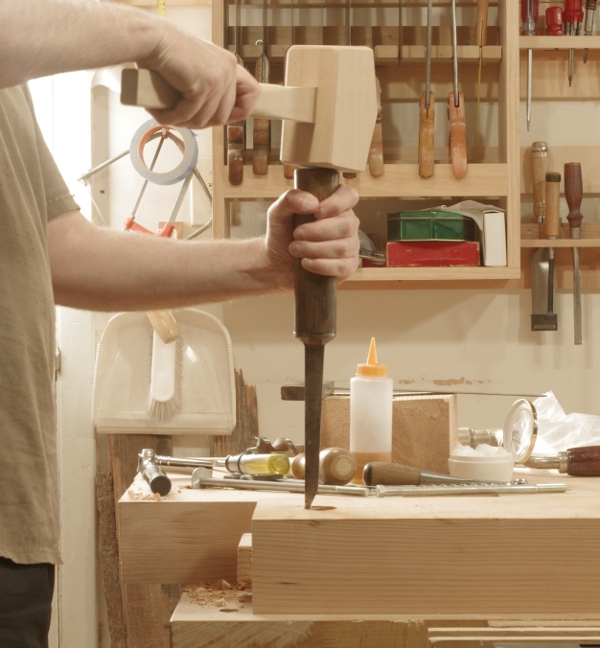
Then I made one side of the hole flat for the nut and washer to register against. This was an easy job with a big “pigsticker” mortise chisel:
Finally, here is how the joint appears in the end with the bolt, nut, and washer in place:
If this looks a little ugly, it is. This side of the stretcher faces the inside, where no one can see it. Therefore, I didn’t bother with anything other than rough planing (especially important to me, given how quickly this wood dulls blades). The mortise shape is somewhat interesting, and that’s something to maybe file away. But on the other side (the face side), it looks like a normal (tight) mortise-and-tenon joint.