Benchtop Alteration: Cause: Surprise Veritas Quick-Release Tail Vise

Just as I was getting ready to get started on a new project (or tool), something pops up. In this case, it’s the following:

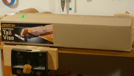
Thanks to Alex, Jasen, Calvin, Rachel, and Paul for giving this to celebrate a, er, “major life change” (sorry for the vagueness, but I prefer not to go into personal stuff much in this blog).

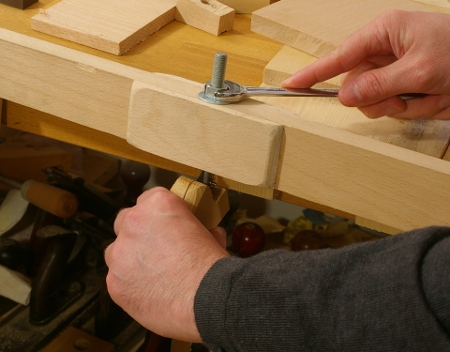
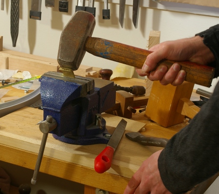
I had a chance to dig it out and look at it today, and you can see that I’ve got to make some decisions on how I want to install this:

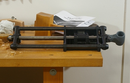
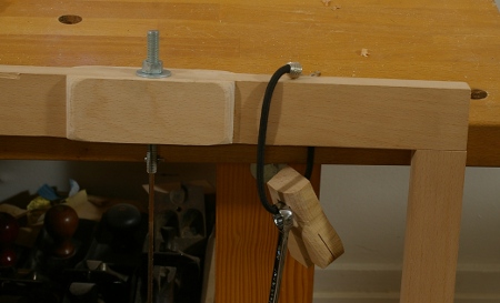
The stock instructions from Lee Valley show mounting the vise jaw as an extension to a bench apron. Of course, I don’t have one of those, nor is my benchtop very thick, and furthermore, my benchtop does not have much overhang.

This overhang is the major issue. It seems that you need a little more than 16″ of overhang on the end of your bench to mount this sucker, or otherwise, it’s going to get in the way of your legs. My bench doesn’t have anywhere near that–it’s more like 6.5″ on each side, so I can’t even just shove the top over.

So if I want to use this vise sometime in the near future, I have to make some sort of serious or semi-serious modification. There are these options:

  • Make a new top. I have enough beech to do this, and I could also look for some reclaimed stuff.
  • Extend the top by replacing the front.
  • Make an entirely new bench. [Ed: This is what I eventually did.]
  • Attempt to make it into a wagon vise.
  • Attempt to make an L-shaped jaw. Unlike the traditional tail vise jaw, this would be rotated 90 degrees. This is kind of a crazy idea but it might just work and it might be the easiest of the options, because the vise only travels 7″ or so.

In any case, there’s some thinking to do, especially because I had wanted to think about what to do about the front overhang. The Gospel of Schwarz says that the front should line up flush with the legs and I agree. I’ve been itching to make this change to my bench but it does require some work. Perhaps making a new bench would be easier, but do I need another bench? It’s tempting to use the current bench as an auxiliary, especially because I like to clamp stuff to its top, and the edge is great for the bench hook.

Oh well. Lots of thinking to do.

[Ed.: Phil Lang provided this link for what Konrad Sauer did.]

New Joinery Saw

In my last post, I was cutting the teeth on a new saw. This one’s got a plate that’s 10″x3″, .020″ thick, and has a milled brass back that has a 1/4″x3/4″ profile. These parts came from Mike Wenzloff, to whom I owe a lot of thanks for not only accommodating what turned out to be kind of a crazy order, but also for providing tips on how to attach the back and other matters.

I’m not sure what to call this saw because it’s somewhere between a dovetail saw and a carcase/small tenon saw. As I mentioned before, it’s got 16 teeth per inch, which is in the range of most dovetail saws, as is the sawplate thickness, but its plate depth is a bit more than more of those.

My goal was to replace the trusty Crown gents saw that I’ve been making most of my joints with. I’ve been happy with the way that saw cuts, and indeed, I’ve made most of my furniture with it, but I wanted more weight and a “nicer” handle. So since I want to cut most of my joinery with this saw, I’m calling it a joinery saw, I guess.

So with the teeth cut, the back shaped and attached, and the blade waxed up, I grabbed the cherry handle from this saw from before, put holes in the right spots, and it was done:

Then I tested it out by slicing the end of a piece of something-or-other to ribbons:

I have to admit, that was a lot of fun.

But projects awaited this saw, so I had to get going on them. The first one I worked on was this box:

It’s a small box meant to hold cards the size of index cards. The walls are made from a block of Arizona Cypress (thanks to Roger Van Maren for bringing this in to Bagathon!), about 3/8″ thick. The bottom is redwood, about 3/32″ thick, sawed out with the frame saw.

I’m not sure what in the world I was thinking, because this wood kind of “crumbles out” rather than tears out. The grain reverses like crazy. I had to make a scratch stock-like tool to scrape out the groove for the bottom. But I guess once you get the hang of it, the end result is nice. And the new saw worked really well for those teeny dovetails.

Cutting New Saw Teeth

When I remark that I’ve cut teeth entirely from scratch on many of my saws, some people think that it either involves stamping, a machine, or some sort of magic trick. It’s nothing of the sort. If a klutz like me can do it on the abomination of a saw vise that I have, anyone can.

It’s actually quite simple because it’s derived from normal saw-sharpening practice. You start with a file with a handle and flat block of wood as described in Lee’s book and any saw sharpening site out there. To get the tooth spacing, make yourself a little guide. I wrote my own PostScript program to do it (check the Plans and Guides page for PDF versions ugh, gotta restore that some time), but I imagine that there are plenty of ways you can do it with several packages.

Get some reading glasses; they help a lot.

Fold the guide over the front jaw of the vise, put the blade in, just peeking over the top, and make a first pass with the file, just filing in a little notch over the top of each line (sorry about the fuzziness, but I just don’t have a macro lens):

Notice that I’m not really getting the spacing spot-on; you can tell from the flats at the tips of the newly-formed teeth. Don’t worry about this on your first pass–you’re going to refine it later on. You don’t even have to worry much about the file itself on the first pass. The one I’m using here is way too big for the final tooth size (this will be a 16TPI saw that I will reveal later). I’m doing this because I don’t want to put unnecessary wear on a relatively expensive small saw file.

After you’re done with the first pass, do a second pass to go deeper. Make an attempt to correct for uneven spacing by putting a little pressure left or right as you’re filing, but use a very light touch; don’t make any extra strokes with the file just to even it out, and don’t press harder than you normally would. You still want to be fairly consistent in the newly-cut tooth valley size. The unevenness will disappear as you make more passes with the file.

In the saw above, the teeth are so small that I went most of the way with my second pass, this time using a file that’s appropriate for the pitch. You can see that the teeth are slightly uneven, but not by extreme amounts:

I then set the teeth, jointed them, and did a final filing. At that point, the teeth were quite even. It’s important to joint and file after you set the teeth because the act of setting the teeth dramatically alters the orientation and shape of the cutting edges. In addition, you’ll often accidentally set the teeth more than you need. A final pass at sharpening helps reduce the set. For the saw above, I used a fine-tooth saw set at its minimal setting, and it was still too much!

Frame Saw: Endless Tweaking

Just when you thought it was safe to go out again, here I go again with the frame saw. This time, I wanted to fix some of the problems I’ve had with the blade-holding hardware. The basic problem is that the bolts I was using were too small for anything reasonable as a cross pin to secure the blade. I bought some 3/8″ bolts and threaded rod to go into the frame, then some stainless steel #4-40 machine screws and nuts to serve as cross pins. I used the same procedure to adapt the hardware as before, so I won’t repeat that.

I thought that I had to enlarge the holes in the frame for the new hardware, but it turns out that I needed to do it to just one of the sides–the other was already big enough (I don’t remember doing it this way). But enlarging the holes means that there’s even more of a weak point in the wood at the very point where it is getting the most stress. Beech is very strong for this application, but I didn’t really want to take any chances, so I resawed and shaped some scraps to bolster that point:

Then I glued them to the frame (with liquid hide glue, of course):

A couple of days passed (while I was working on other stuff), and I figured it was best to let the glue cure a fair amount anyway. When I came back to it, I decided that I’d also do something about the difficulty I’d been having keeping the blade straight while tensioning. It turns out that there’s a simple solution. I grabbed a cutoff from the stack (looks like this came from saw handle project) and sloppily cut a kerf halfway down the center:

To use it, just slide it over the blade when you’re tightening it up:

With these changes in place, I can get the blade much tighter with less work.

Oh, in case you’re wondering why there is a the hole in the blade securer, it’s an experiment in keeping everything together while in storage:

Making a Marking Gauge

I made a marking gauge a while back, complete with captive wedge and everything. For a long time, I didn’t have a cutter for its arm, so it wasn’t very useful. Then at some point, I made a cutter out of a section of an old saw, and it was then a working tool. The problem was that I never used it, and after a while, I realized that I never used it because I was always reaching for my gauges with thumbscrews. I guess I didn’t like the captive wedge.

To fix this, I decided to ditch the wedge and retrofit a thumbscrew. I bought all of the hardware necessary and immediately proceeded to bore too small of a hole for the screw insert, and this ultimately ruined the fence part of the gauge. I removed the screw insert, gave up for the day, and sulked:

The next day, I milled a new piece of beech to thickness, cut it to size, and mortised a new hole for the fence:

Standard through-mortise procedure applies: Cut halfway through on each side. Easy enough; then I roughed out the fence shape with my new saw (I’m using it more than I thought I would):

I finished the shaping with my saw rasp and some sandpaper–nothing new there.

In all of the thumbscrew-model marking gauges I’ve seen (the metal screws, that is), there’s a piece of metal acting as a guard between the screw and wooden parts. I don’t know what to call this, so I’m calling it a “saddle,” because it’s usually a U-shaped thing that fits over the wood.

I cut off a piece of brass from some stock I had lying around, put it in a vise, and smacked it with a hammer to try to form it. I guess I was expecting it to be a lot softer, because nothing much happened when I did that. So I took out my little sledgehammer and gave it a pounding. I don’t know if this is the way you’re “supposed” to do stuff like this, but it worked:

After some filing, it fit perfectly.

Then I turned my attention to boring the hole for the screw insert. I had already drilled a small pilot hole before shaping, so keeping the bit straight wasn’t a problem, and I’d also learned from my previous hamfistedness that I needed to use a #7 bit, not a #6 bit. Fortunately, I had one:

Notice the finished saddle piece at the right here.

After going to the correct depth with the #7 bit, I finished going all the way through with a #5 bit, then I used a large furniture connector driven by a ratchet to drive in the screw insert:

To finish it, all I had to do was hack the thumbscrew to a proper length and put everything together:

Immediately after putting everything together, I realized that maybe the marking gauge with a thumbscrew and wedged cutter is not as simple of a tool to make as it seems. That’s because there is a limitation of this particular configuration that I hadn’t thought about before, namely, that the cutter can’t be set less than about 3/16″ away from the fence. There are two causes here:

  • I put the wedge on the inside of the cutter rather than the outside.
  • The saddle introduces yet more buffer space. That wouldn’t have been a problem if I put the saddle on the side, like some other marking gauges, but I didn’t like the fact that the arm had a little play in that configuration.

How interesting! I know how to overcome both of these issues, but I’m not going to bother for this particular gauge. It’s done and ready to use.

[Edit: See this post for how I fixed the second problem listed above. Also, see this post for a more advanced approach to the problem.]Links not available at the moment, but they are the tweaking and panel gauge links, which might not be restored yet.

[Edit: Bob Rozaieski has put up a video of making a French style marking gauge. Check it out here.]