Half-Blind Dovetail With Mitered Shoulder: What Was I Smoking?

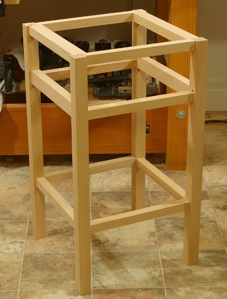
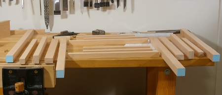
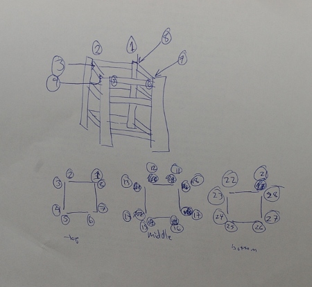
This weekend, I started work on a new project for the shop that will soon be desperately needed. As with nearly all of my other projects, I drew it up and decided on the joint–dovetails for a carcase frame, of course. I recalled that I’d seen a mitered-shouldered through dovetail joint, did a little bit of reading on it, and decided that it would be a neat one to try.

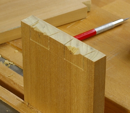
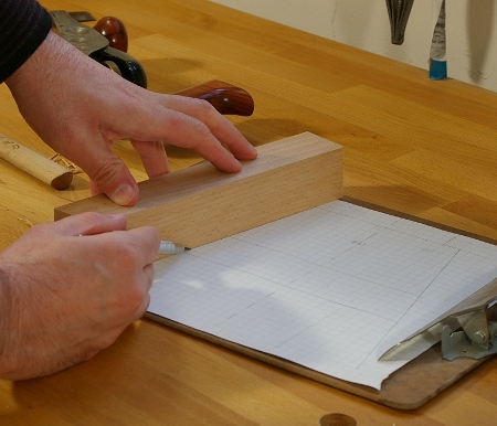
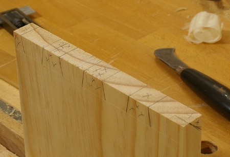
Except that I decided to make it a half-blind version. I clearly did not plan this one out very well, but I was very careful when laying out the tailboard, making sure to put the Xs in the waste parts, and indicating where the shoulder would miter. I thought that this would be a piece of cake, I’d just rough out the miter on both pieces when fitting the pinboard, then fine-tune it later. After all, both miters would be the same angle, right? Right?

What could possibly go wrong?

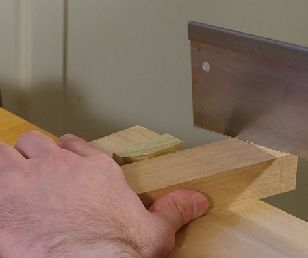
It should have occurred to me that I’d screwed up somewhere simply based on the fact that as I was sawing down the pinboard the first time, I managed to saw on the wrong side of one of the lines. At the time, I chalked this up to not having taken a break, the anticipation of the big game soon to start, and the fact that a really annoying song was playing on the radio when I made the mistake.

Unfortunately, it was actually fate trying to warn me, and I didn’t listen. Instead, I just sawed off the end of the pinboard, marked it out again, and went upstairs to watch the game.

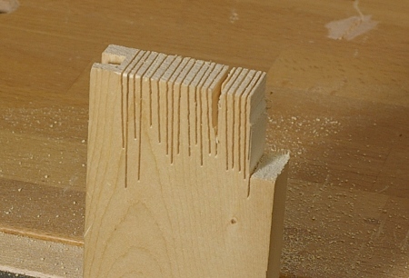
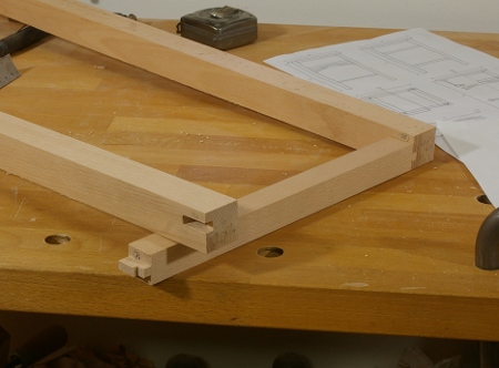
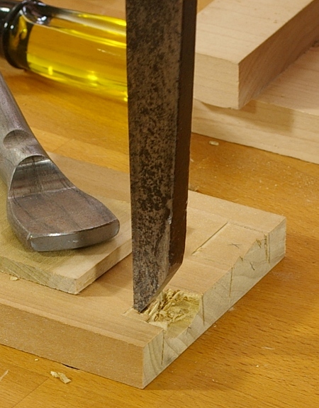
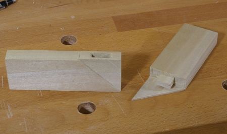
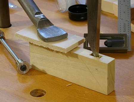
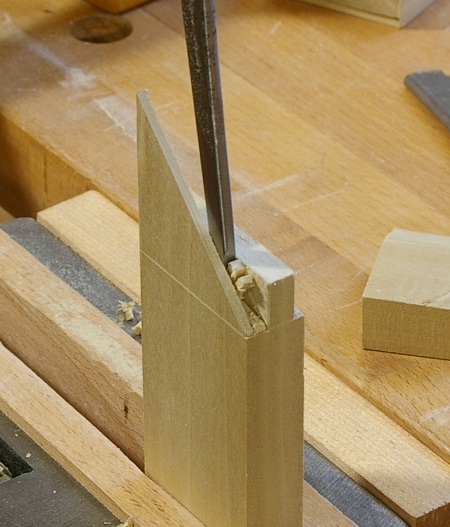
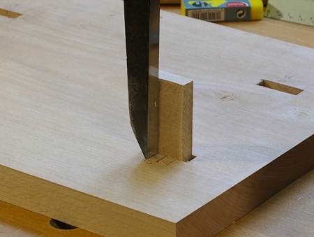
When I came back the next day, I managed to saw everything correctly, popped out most of the waste, and then, to make sure that the pins and tails fit, sawed off a small amount of the miter on the shoulders.

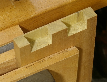
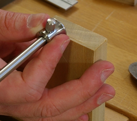
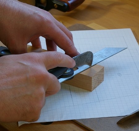
The tails and pins fit without paring. That was as far as the good times went, though, because that’s when I got out my other T-bevel, set it to 45 degrees, and went to mark out the final miter for the corner.

Something wasn’t right. Why didn’t the miter line up to the corners of the joint? Everything should be the same width and thickness, ri–oh, wait. Duh, on a half-blind dovetail, unless the tailboard is thinner than the pinboard, the joint profile will not be square, and that’s not going to be a 45-degree miter. Furthermore, you can’t cut your miter beyond the half-blind portion if you’ve already done your tailboard, because the tailboard probably doesn’t extend that far.

I don’t know how long I stared at that thing, trying to figure out what to do. I didn’t know if I should try to salvage it, or just hang my head in shame and start anew with something a little more conventional.

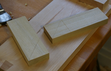
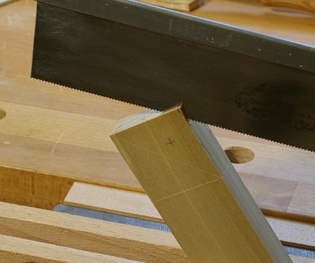
Masochist that I am, I chose to try to salvage it because I hadn’t cut beyond the half-blind portion of the shoulder. For another equally long time, I tried to figure out what this was going to look like. I’m not sure I had an idea, but in any case, I started by marking out the miter on the pinboard from the pin base to the half-blind line (or whatever it’s called). Then I measured that angle: 50 degrees. That seemed really fishy to me, but I set my T-bevel to the 40 degrees necessary to complete the full 90 degrees and marked it lightly on the tailboard.

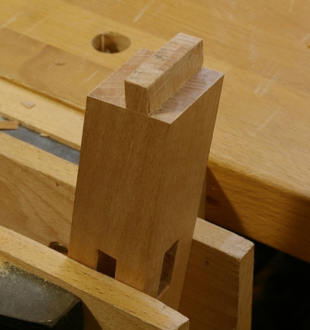
I banged the pieces together a little. Of course, I dented the beautifully-surfaced face that my newly-acquired Taiwanese plane had made because I used a buffer scrap that was too small. At this point, I didn’t care about that anymore, I just wanted those two miter lines to be perpendicular, and to my surprise, they were.

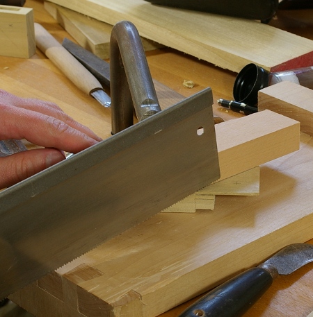
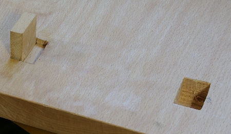
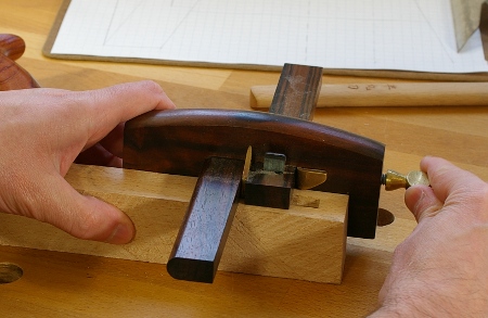
So I pulled the pieces apart and shaved down to the miter lines with my Veritas mini shoulder plane (this worked remarkably well). And then I banged the pieces together to see if they drew tight.

They didn’t, of course. In addition to this unsightly gap, there were also big gaps at the pinboard baseline, and I suspected that they might be related. I put the work down for the night and went off to freak out about something else.

When I dragged myself back the next morning, I tried jamming a piece of paper into the miter gap. It went in only halfway, so I pulled the pieces apart and checked the square of the long edge to the mitered surface. It was slightly out of square–kind of convex on the top. I pared it out (maybe making it a little convex in the process) and tried again.

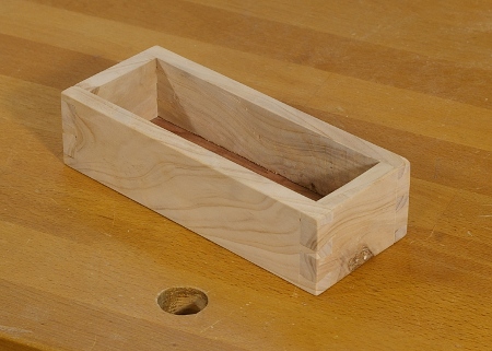
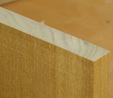
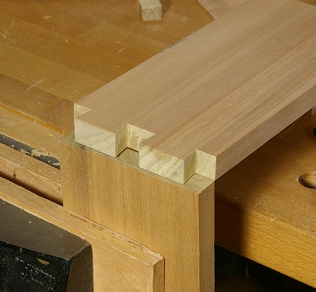
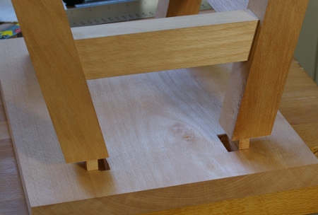
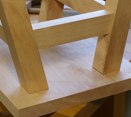
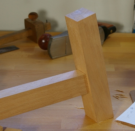
I almost fainted. There’s no way that this should have drawn tight given the number of errors that I made.

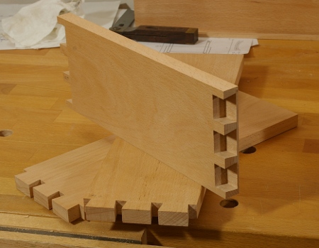
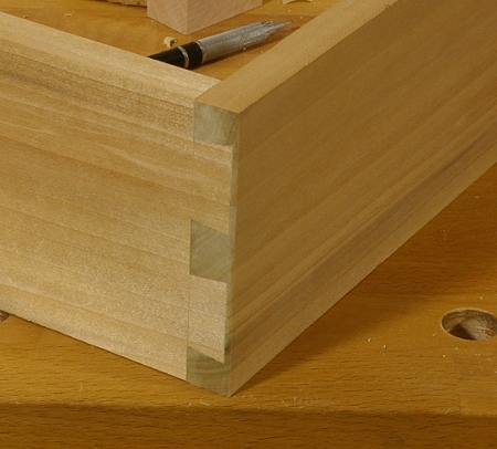
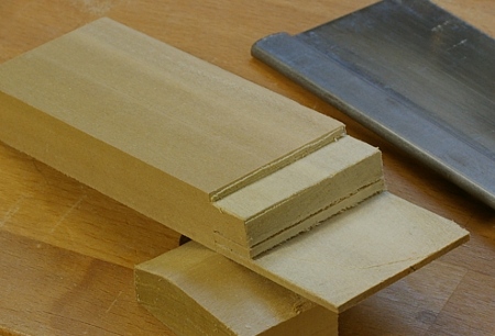
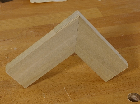
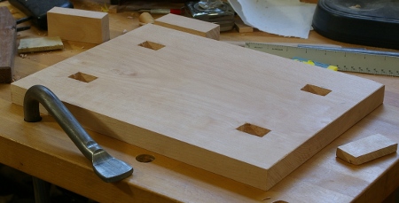
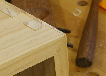
The preceding photo was taken after I pared off the excess of the pinboard on the end–I wanted to see what it looked like. I’m afraid to admit this, but I sort of like it. Only I wish I could say that I’d actually planned it that way.

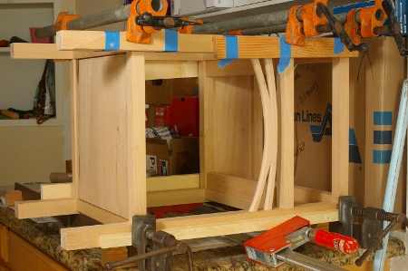
Now I have to make three more. Guh.

New Joinery Saw

In my last post, I was cutting the teeth on a new saw. This one’s got a plate that’s 10″x3″, .020″ thick, and has a milled brass back that has a 1/4″x3/4″ profile. These parts came from Mike Wenzloff, to whom I owe a lot of thanks for not only accommodating what turned out to be kind of a crazy order, but also for providing tips on how to attach the back and other matters.

I’m not sure what to call this saw because it’s somewhere between a dovetail saw and a carcase/small tenon saw. As I mentioned before, it’s got 16 teeth per inch, which is in the range of most dovetail saws, as is the sawplate thickness, but its plate depth is a bit more than more of those.

My goal was to replace the trusty Crown gents saw that I’ve been making most of my joints with. I’ve been happy with the way that saw cuts, and indeed, I’ve made most of my furniture with it, but I wanted more weight and a “nicer” handle. So since I want to cut most of my joinery with this saw, I’m calling it a joinery saw, I guess.

So with the teeth cut, the back shaped and attached, and the blade waxed up, I grabbed the cherry handle from this saw from before, put holes in the right spots, and it was done:

Then I tested it out by slicing the end of a piece of something-or-other to ribbons:

I have to admit, that was a lot of fun.

But projects awaited this saw, so I had to get going on them. The first one I worked on was this box:

It’s a small box meant to hold cards the size of index cards. The walls are made from a block of Arizona Cypress (thanks to Roger Van Maren for bringing this in to Bagathon!), about 3/8″ thick. The bottom is redwood, about 3/32″ thick, sawed out with the frame saw.

I’m not sure what in the world I was thinking, because this wood kind of “crumbles out” rather than tears out. The grain reverses like crazy. I had to make a scratch stock-like tool to scrape out the groove for the bottom. But I guess once you get the hang of it, the end result is nice. And the new saw worked really well for those teeny dovetails.

Nightstand: Frame Glueup, Drawer Started

With the shelf made, the front and back frames glued and set for a few days, there was nothing left to do but to glue up the whole frame.

I never have many pictures of the glueup process, because it’s really the only time when time matters a lot. When you’re under pressure to get all of the parts into the right places and into the frame before the glue starts to set, there really isn’t any chance to take photos. In addition, all of my shots are done on a tripod and involve long exposures because the lighting is really bad in the shop, and I can’t hold the camera steady anyway. Finally, my hands tend to get a little sticky with the liquid hide glue, so I don’t want to get any of that on my camera.

I can, however, take pictures of the piece when I’m finished and it’s in the clamps. Thanks to Jasen for lending me the pipe clamps and K-clamp:

This will be ready for varnish in a few days.

The two other remaining components of the project are the top and the drawer. I’ve got the boards for the drawer down to size and cut the half-blind dovetails for the front:

I’m a little concerned about the clearance in the front, it’s possible that this may be too tight of a fit. Depending on how it works out, I may knock off 1/32″ or less off of the faces of each side, because I don’t want this thing getting stuck inside the frame if the boards expand a little.

Though half of the joints are made for the drawer, I’m almost done, because the rear joints will be through dovetails, which are much faster to make. In addition, it’s likely that I will cut only two tails back there to keep it simple. Then there’s fitting the drawer bottom and finally, the drawer pull.

I may be finished cutting wood on the project this weekend.

Nightstand: Frame Joinery Complete

The nightstand project requires 24 mortise-and-tenon joints for the external frame, four for the drawer runner supports, and four more for the decoration on the front. I’ve cut all of these except the ones for the decoration. Here’s a shot of a test-fit of the external frame (without the runners):

My speed improved significantly while making all of these joints. When I started the first one, it was taking me as long as 45 minutes to make one. Most of the time was spent paring off little bits of the tenons, most annoyingly, on the shoulders. By the time I did the drawer runner pieces, I was doing them in under 30 minutes. (Yeah, the pros do them six times faster, but I’m not a pro.) What’s more important to me than speed is accuracy, and that improved tremendously, too. All of my tenons now seem to fit right off the saw. The only paring I need to do is still that little bit on the shoulders, but it’s going faster now. I’m using the mystery chisel for that because a 1.5″ chisel has a lot of registration area. It really seems to be holding its edge well.

I also managed to cut myself with my dovetail saw. Ouch, I didn’t realize it was that sharp.

This project’s joints are a motley bunch. I’m using different offsets at different locations to try to maximize contact based on constraints of panel and corner placement. Some have haunches to improve alignment. Here’s a shot of the middle frame layer, the one that the drawers will rest upon, showing the drawer support runners that I just finished up today:

The runners, back, and right side are depicted in their intended final configuration, and the front and left sides are not attached. When finished, the sides will have rabbets with grooves for where the side panels will rest, and the rear will have a groove for the rear panel.

This is a shot of the current state of the parts and parts-to-be:

The mostly-complete parts (18 of them) are in the front, and the number of pieces in the back indicate that I still have a fair amount of work to do here:

  • join the top
  • join and rabbet the shelf
  • mill the pieces for the drawer and make the drawer
  • mill the panels
  • groove the frame for the panels and shelf
  • make the drawer pull (wood for drawer pull not shown here)
  • glue up everything
  • varnish

What to do next? Well, I’d better pick something. I do have a deadline for this piece. It’ll be either the decoration or joining the shelves, I think.

Nightstand: Joinery Started

Yesterday, I finished milling all of the nightstand pieces except the drawer and panels. Looking back, it looks like it took me two and a half weeks to do all of it. It might have gone a little faster if the wood hadn’t moved so much after resawing. I had to go to another board to get enough consistent material for the top and shelf. The shelf was especially bad; I had originally intended that segment to be the top, but I introduced so much twist into the board when milling that I had to thin it out.

I wonder how much faster this would have gone with a bandsaw. When I think about it, probably not too much, because it would still require planing and more flattening, and if I get faster at that stuff, then that eliminates a big chunk of the time I spent on this. (The resawing, that’s a different story.)

But that’s mostly behind me now, so I arranged the pieces I had into the orientations that I’ll use for the frame layout:

It was a little tricky to get everything oriented so that none of the grain will stick out like a sore thumb. Some of the faces have ray fleck because they’re cut on the radial plane (as if they were from a quartersawn board), and although this pattern looks great in beech, I didn’t want to make it stand out on this piece. In addition, due to the various cuts on the board, the visible ray thicknesses vary slightly from piece to piece, so I matched them up on each side of the nightstand as much as possible.

With that done, I labeled each piece, made a map of the joints, and was able to do the top rear joints today–two little haunched mortise-and-tenon joints!

It’s such a relief to be at this stage now. My worries now are essentially how I should go about cutting these things. I started with the rear top because no one is ever going to see those, so if I mess them up, it’s okay. I guess I’ll finish off the rest of the joints around the top and work my way down to the next level, so that I can mark off the distances from existing joints as I go.

The joints will be a mixed bag of mortise-and-tenon joints. I’m using haunched ones at the top because I want more registration surface and I want to avoid blowing out mortises at the end (I was very careful this time). In the middle and the bottom, there will be more basic mortise-and-tenons, but the tenon lengths will vary. I have this in the drawing, or at least I pretend I do.

Making a map of the joints helps a lot. I had a mental one for the stool project, but because there are three times as many joints in this one, I decided to scribble it down on paper. And what an incredibly professional scribble it is.

You can see how I first drew it in 3D with circles and arrows (and a paragraph on the back of each one, har), but gave up on that and just broke it into top, middle, and bottom levels. I give each joint a number and when I cut a joint, I put the number on each piece. Here, the numbers go counter-clockwise around the frame from top to bottom. At first, I was numbering consecutively when moving from level to level, but then I decided it might be easier to just add ten to the starting number for the previous level and go about it that way. At the very least, it makes it easy to identify the level to which the joint belongs.

A First Half-Blind Dovetail Joint

Wouldn’t you know it, as soon as I’m ready to post something on dovetails, Leif over at Norse Woodsmith has already done one today. That’s deja-vu in more than one way.

Well, in any case, the story goes something like this: I’ve got some projects on the horizon that use half-blind dovetails, and it turns out that I haven’t gotten around to making one yet. Being the “cautious” guy that I am, I decided it would be good to try out a practice joint to find new and exciting ways to screw up.

So I grabbed a practice through dovetail joint that I’d made in some yellow-poplar long ago, sawed out that joint, and used the shooting board to get the ends smooth. The first step was to get the pinboard marked. I picked a depth for the tails to extend into the pinboard, and marked that on the edge of the board, from the front. Then I set another gauge (well, the other end of the Lee Valley mini wheel gauge) to slightly more than the width of the tailboard, and marked it on one side (only one side is necessary because you don’t cut into the other side). The marks are barely visible in this photo, but you get the idea.

Then I worked on the tailboard, marking the tail length from the gauge setting used for the depth into the pinboard (the line on the top near the back in the preceding photo). There’s nothing special about the tailboard, and it took about as long as tailboards usually take me these days.

With the tailboard in hand, I marked the pin profile into the pinboard:

I sawed the diagonal between the two initial lines in the first photo in this post. So far, I’d been pretty much following the instructions in Korn’s book, down to putting the Xs on the waste parts. However, for the next part, I decided that I didn’t want to try to drill out most of the waste. First I tried paring across the grain (you can see the diagonal sawcuts in the front of this photo, too):

It didn’t take long for me to realize that this was sort of a stupid idea, so I switched tactics. In other words, I just grabbed the trusty pigsticker and started whacking and prying away:

This was highly effective, and got most of the job done quickly. At a certain point, though, you have to switch to paring so that you get smooth, clean lines. It seems that the trick to doing this joint quickly is to be good enough with the big chisel to get as close as possible to the paring step. I was okay at this, but not great. So there’s something to practice.

But before long, I’d finished paring (even without a skew chisel or a special dovetail chisel), and I had a finished pinboard:

OK, I guess it’s good that this looks like a pinboard, but does it fit? Surprisingly, yes, and with no additional tweaking. I banged the joint together and planed the pinboard flush, and here’s what I got:

I’m a little uneasy about the way this turned out, because it doesn’t seem like I made any mistakes. My fear is that I’ll make a mistake when doing a project because I didn’t know about it earlier. But then again, I did realize something about half-blind dovetails that I didn’t think about before: You can actually make a lot of mistakes on this joint and still have it turn out fine, because it shows a little more than half of the junctions that a through dovetail does. Be careful in paring down the thin edge near the face, and that’s about it.

Making a Mitered-Face Mortise-and-Tenon Joint

On my visit to Taiwan in December, I had a chance to look at a family cabinet that was probably made in the 20s or 30s on the island. No one could tell me a lot about it, but the thing that fascinated me the most was that it had a joint that I did not recall ever seeing in the wild. Then on the trip to Sanyi, I saw a new cabinet with the same joint. When I got home, I looked for it in my books, but I did not find it. The only thing I saw that was similar was in a book on Japanese construction joinery.

For lack of a better name (or research, at least for the moment), I’m going to call this a mortise-and-tenon joint with a mitered face, because that’s what it is:

The ones I saw have through tenons, as opposed to this one, which does not, but it’s basically all the same idea.

I was really eager to make one when I got back from Taiwan, but I didn’t have the chance because I was too busy making other stuff. But right now, I’m varnishing both the bookshelf and the stool, and I don’t have the next project designed yet, so I thought I’d try some new joints. I made my first one yesterday, but I wasn’t entirely successful, so I tried again today.

The first thing I did was mark out the miters on the mortise and tenon pieces. I accidentally marked a shoulder on the face of the tenon piece here. The shoulder should be marked all the way around except for on the face with the miter. Somehow I will forgive myself for this:

Then I marked the face thickness around the edges of the mortise and tenon pieces (don’t mark on the bottom of the mortise, though). Notice the use of the mini wheel marking gauge that Lee Valley “made” everyone buy last year:

With this done, I set aside the tenon piece and chopped the mortise. A very important note here: For the distance between the inside of the face and the mortise, make sure that it’s at least a little bit bigger than the width of your smallest chisel! My smallest chisel is 1/8″. I made this mistake on my first attempt.

Chopping the mortise was easy as usual with a pigsticker, especially on yellow-poplar. On my first attempt at the joint, I blew out the sides of the mortise, but I managed to avoid that today:

(I felt that it was pretty important to mark the waste sections of the mortise and tenon with an “x,” because the miter makes things a little complicated.)

With the mortise chopped, I set my mortise gauge from the mortise, then set the mortise piece aside and turned to the tenon. After marking the tenon width, I sawed the cheek of the miter, then the inside cheek of the tenon, then finally, the outside (back) cheek of the tenon. I did not saw any shoulders yet.

All three cheek cuts go down to the shoulder line. Again, the shoulder line on the face above is an error. It should appear on the other three sides, but not this one.

Working from the back of the tenon, I sawed the rear shoulder first, then sawed the top of the tenon to the proper height. I continued the tenon-height cut through the waste between the face and the tenon, so I was left with this:

I decided to saw the miter on the tenon next. During my first attempt yesterday, I found it pretty difficult to do freehand, so this time, I clamped a piece of scrap across the knife line and used that as a guide for a crosscut saw:

This worked surprisingly well, and I also used the same technique for the mortise (but I’m not at that point yet).

Next was to finish the tenon. I had to remove all of the waste between the face and the tenon. I did this by first chopping down along the grain, then paring the pieces out (notice the 1/8″ chisel here–remember how I said that the width of your smallest chisel is important?):

I also needed to remove the ends of the tenon to make the length fit the mortise. I used the same technique, but I was also able to make partial sawcuts, which helped a lot.

With the tenon finished, I turned back to the mortise. I first sawed down the cheek of the miter, where the tenon piece’s face fits. I cut only down to the knife line that marked the miter, and then I used the miter-sawing technique above to remove the piece. A little paring and cleanup was necessary with a chisel and my rabbet plane, but this time, it all fit together perfectly:

Yeah, oops about that shoulder line again. The end of the mortise piece sits a little proud of the end. You can plane this off. I suppose that for a full frame, you’d want to cut the pieces with the mortises slightly longer than you need, so that you can measure your overall width from the inside and plane off the excess. Or maybe not, I’m not sure.

It’s unlikely that I will use this joint in a project soon, but it’s nice to have around. But other than the lack of a suitable application, I really should get a smaller mortise chisel if I’m going to be working in thin frames like this. I really pushed the limits of what I was able to do with my W. Butcher 9/32″ chisel. If it were any wider, I would not have been able to fit the mortise and tenon inside the space available with the face and its buffer area factored in. So maybe I’ll be on the hunt for yet another pigsticker now, a 3/16″ or similar. (Sigh.)

Stool: Messing Up and Repairing Mortises (again)

In preparing to attach the stool’s top to the leg frame, I first measured, marked, and cut angled tenons on the tops of the legs. I used the scale drawing again as a guide. Here’s a photo of an angled tenon before I finished cutting the shoulders at the long ends:

That was a fairly simple task, even though I was cutting the tenon before the mortise. To make sure that the tenon fit, I chopped a mortise in a piece of scrap and test-fit.

Then I assembled the frame and double-checked the distance between the tenons, and carefully laid out the lines that I’d chop against on the stool top. Then I broke my mallet chopping the mortises (as described in the preceding post), so I had to wait for the glue to set on the mallet repair until I could get going again. When I did, I was excited to see a test fit.

I was not so excited to discover my latest boneup:

Arrgh. I had chopped the mortises on the wrong side of the lines. I have got to get more careful with this. It’s, what, the third time I’ve done that in two months? I was pretty discouraged, so I took a break while I tried to figure out what I would do about it. Also, I was hungry.

Then I went back to the shop and cut out a piece of beech to the same thickness as the tenons. I inserted this into the mortise, and then extended the mortise (this time in the correct location) by chopping against the side of the inserted section:

After doing this for all four mortises, I had the following:

And then I did a test fit to make sure that I’d actually chopped them in the correct place this time:

Phew. It fits, and there’s only a small void showing on the underside of the stool. But if left and glued up like this, there would probably be a tendency to rack, because the legs could conceptually slide around. Therefore, I had to fill in the originally-cut side of the mortise.

I sliced off a small section of the piece of beech I used to register the chisel when chopping the correct mortise, and glued that on one side where I’d originally chopped the mortise. Then, on the other side, I inserted the section again to “clamp” it in place as the glue dried:

After each mortise got its repair, I did another test fit. Incredibly, it seems to have worked. Now I just have to finish off the edges on the components and glue up.

Stool: Frame Joinery Complete

I managed to get a chunk of shop time in today, and finished the remaining mortise-and-tenon joints in the components that make up the stool’s frame.

After doing all of the angled joints first, I found myself relieved when I got to the normal mortise-and-tenon joints. The tenons aren’t any more difficult to cut on the angled joints, but you do have to pay attention when making the mortises. The normal ones are blissfully mindless, which probably explains how I managed to chop a mortise in the wrong place again. I was able to fudge a way around that error. One of these days, I’m going to learn to be careful where I put those things.

With each of the joints complete, I made a test-fit, and it looks like everything works out pretty well:

The only remaining work to be done here is to cut the top to its final size, and then to attach the top to the legs. That latter part will involve angled tenons, yay.

I have been debating on whether I should chamfer the edges of frame pieces. I was originally planning to, but I kind of like the lines on this thing as it stands now.

Another debate is now if I should make a new mallet or not. The Thagomizer is a great mallet that has worked perfectly for me with the scale of joinery that I’ve been doing so far. However, for the first time, I found myself wishing that maybe I had a little more mass and leverage while chopping the larger mortises in this beech. If I ever do make one, though, it won’t be for a long time. I have too much to do.

Stool: Cutting an Angled Mortise and Tenon Joint

In my last post, I sawed the angle at the bottom of one of the legs of the stool. Now, I felt it was time to try one of the angled mortise-and-tenon joints with which half of the stretchers will be attached to the legs.

I again went back to my scale drawing and marked out where the mortise would go:

Unlike most of the joints I’ve made in the past, I couldn’t use one mortise gauge to mark both the mortise and the tenon. This is because a 1″ wide stretcher will meet a 1.5″ leg, so there has to be about a quarter-inch of space on either side of the stretcher so that it’s centered.

So I had to use a little bit of actual calculated measurement for this. Fans of the metric system may want to skip to the next paragraph. My mortise chisel is 3/8″, and half of that is 3/16″. The leg is 1.5″, or 24/16″, and half of that is 12/16″. That means that to center the mortise, I needed to align the near edge at 9/16″ (12/16″ – 3/16″). (Gee, I guess there was a good reason for not going with the 7/16″ chisel for this project after all.)

I used a marking gauge set at 9/16″ to scribe just one line for the mortise. From that point, it’s just like chopping a regular mortise, except at the ends. This mortise is not rectangular, but rather, a parallelogram. I used my sliding T-bevel to get the approximate angle on both ends while chopping.

The preceding image is actually a bit of a fib, because when I was doing this, my hands were switched (left on the chisel, right on the bevel), because I use the mallet with my right hand. I think you get the idea, though.

Next up was to saw the tenon. For this, I set up the mortise marking gauge. The first thing I did was to chop a mortise dead center in a 1″ width into a piece of scrap. Then I stuck the knives into the mortise and set the gauge:

Notice that this piece of scrap is roughly sawn on the face that you see here and it’s actually a little more than 1″ wide. This doesn’t matter, because the reference face of the scrap is flat, and I scribed a line at 1″ on the top, but I admit that it makes for a confusing picture.

Proceeding to the actual tenon, I went back to my scale drawing and marked out the limits of the tenon shoulder. When I had a mark in place, I used the sliding T-bevel again to mark the shoulder:

After using the mortise gauge set earlier, it looked just like almost any other tenon, except that the shoulder was at an angle. Sawing at angles turned out to be tricker than I thought, but then I remembered another tip from that book I mentioned in my last post; you can put a piece of scrap with one side relieved between the work and whatever you’re holding it against to bring it roughly square. This worked surprisingly well:

And soon, I test-fit my first angled mortise-and-tenon joint:

There’s a little gap in the joint in this photo; the test-fit revealed that I still had a little more trimming to do on the shoulder.

Three more of these plus four non-angled mortise-and-tenon joints to make, and the frame will be together, ready for its joinery to the top.