Stool: Cutting an Angled Mortise and Tenon Joint

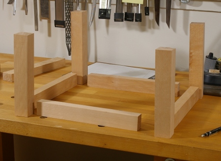
In my last post, I sawed the angle at the bottom of one of the legs of the stool. Now, I felt it was time to try one of the angled mortise-and-tenon joints with which half of the stretchers will be attached to the legs.

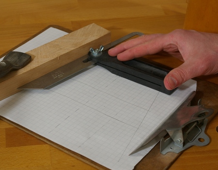
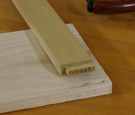
I again went back to my scale drawing and marked out where the mortise would go:

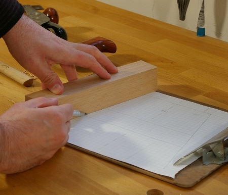
Unlike most of the joints I’ve made in the past, I couldn’t use one mortise gauge to mark both the mortise and the tenon. This is because a 1″ wide stretcher will meet a 1.5″ leg, so there has to be about a quarter-inch of space on either side of the stretcher so that it’s centered.

So I had to use a little bit of actual calculated measurement for this. Fans of the metric system may want to skip to the next paragraph. My mortise chisel is 3/8″, and half of that is 3/16″. The leg is 1.5″, or 24/16″, and half of that is 12/16″. That means that to center the mortise, I needed to align the near edge at 9/16″ (12/16″ – 3/16″). (Gee, I guess there was a good reason for not going with the 7/16″ chisel for this project after all.)

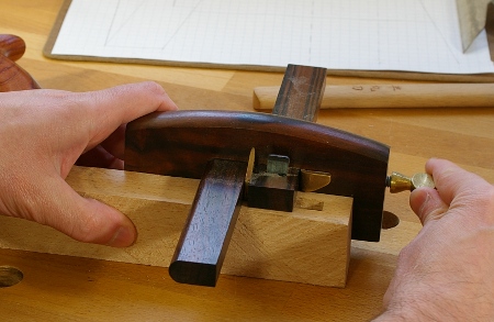
I used a marking gauge set at 9/16″ to scribe just one line for the mortise. From that point, it’s just like chopping a regular mortise, except at the ends. This mortise is not rectangular, but rather, a parallelogram. I used my sliding T-bevel to get the approximate angle on both ends while chopping.

The preceding image is actually a bit of a fib, because when I was doing this, my hands were switched (left on the chisel, right on the bevel), because I use the mallet with my right hand. I think you get the idea, though.

Next up was to saw the tenon. For this, I set up the mortise marking gauge. The first thing I did was to chop a mortise dead center in a 1″ width into a piece of scrap. Then I stuck the knives into the mortise and set the gauge:

Notice that this piece of scrap is roughly sawn on the face that you see here and it’s actually a little more than 1″ wide. This doesn’t matter, because the reference face of the scrap is flat, and I scribed a line at 1″ on the top, but I admit that it makes for a confusing picture.

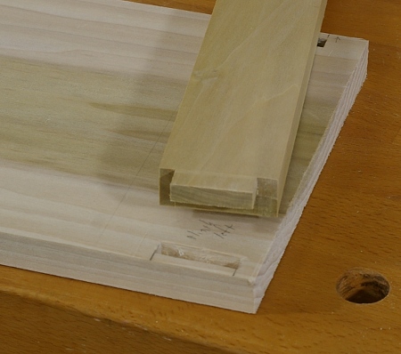
Proceeding to the actual tenon, I went back to my scale drawing and marked out the limits of the tenon shoulder. When I had a mark in place, I used the sliding T-bevel again to mark the shoulder:

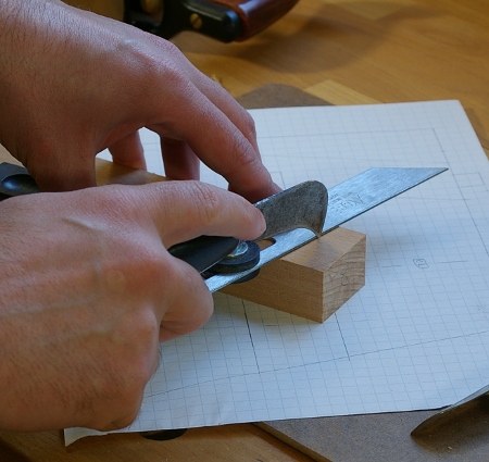
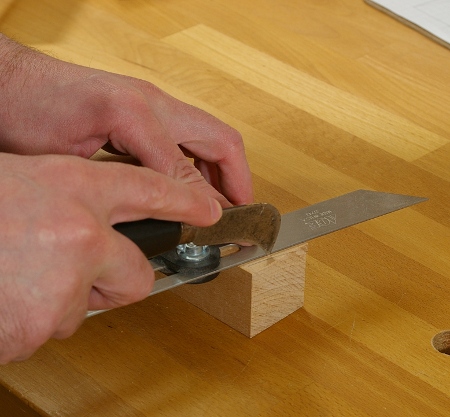
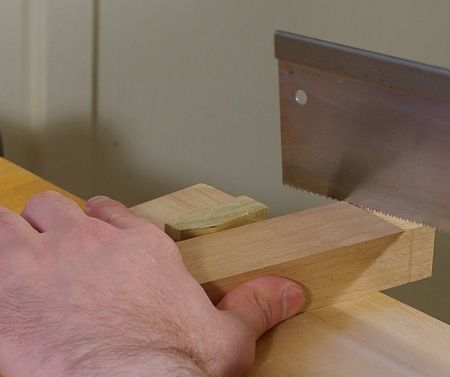
After using the mortise gauge set earlier, it looked just like almost any other tenon, except that the shoulder was at an angle. Sawing at angles turned out to be tricker than I thought, but then I remembered another tip from that book I mentioned in my last post; you can put a piece of scrap with one side relieved between the work and whatever you’re holding it against to bring it roughly square. This worked surprisingly well:

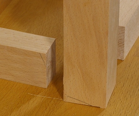
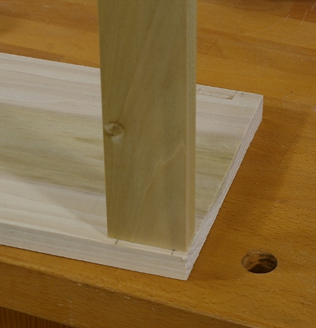
And soon, I test-fit my first angled mortise-and-tenon joint:

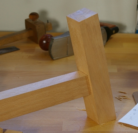
There’s a little gap in the joint in this photo; the test-fit revealed that I still had a little more trimming to do on the shoulder.

Three more of these plus four non-angled mortise-and-tenon joints to make, and the frame will be together, ready for its joinery to the top.

Stool: Setting Angles, Arranging Joints

To prepare for the joinery for the stool’s frame, I needed to come to terms with the angles at which I was going to set the angled mortise-and-tenon joints. Since I’ve never done one of these at an angle before, I felt that I might take a little extra time in preparing the various tools necessary to make the joints.

The first step was to create a full-scale drawing of the joint. Interestingly enough, a joinery book I have also says to do this, but I must confess that I didn’t read that before I’d gone through with the process. As I drew up this thing on graph paper, I realized that I had goofed up some of the critical marked measurements on the computer drawing, though the image of the stool itself was correct. I might go back and fix this in the image that I posted before, but I’ve got other stuff to do now.

With the drawing on a clipboard and a straight board clamped to one side of the angle on the drawing, I set a sliding T-bevel:

After this was set, I realized that I was getting a little ahead of myself, because I hadn’t yet come up with an arrangement for the frame pieces. So I did that:

Then I marked each piece with its position. As an additional indicator, I also roughly marked where the wood will be cut at an angle, so that I don’t accidentally cut an angle where it’s supposed to be straight:

In the preceding image, the piece on the left is a stretcher, and the center is a leg, which will tilt to the left. The marks here indicate the way the stretcher will meet the leg, and how the leg will rest on the floor.

With all of this setting and marking done, I precisely marked the bottom of one of the legs with the T-bevel and a marking knife:

Finally, I sawed it. I don’t have a photo of that, but I guess you’ve seen pics of me sawing stuff before.

Next time, I’ll get down to the business of cutting the joints.

Bookshelf: Munging Mortises

I cut the other dovetail joint for the top of the bookshelf and was feelin’ pretty good about it, and I thought that it might be a good time to start on some of the stretcher pieces that will provide the rest of the racking resistance. There will be three of them, two in the back, and one at the front at the bottom that will be a plinth (“kickboard”) piece.

The mortise in the back near the bottom was my first target, and I proceeded immediately to chop in the wrong place. I didn’t realize this until I had been away from it for a while, so when I came back, I extended it upward until it was in the right spot. You can see it here with its matching tenon:

Thankfully, it will not be visible when this project is complete, but I really have to make this lesson count for something.

I chopped the mortise on the other side and cut its tenon without a hitch, so I was again feeling pretty good about myself, so I decided to go after the plinth next. And, of course, I went straight out and chopped that one in the wrong place, too. You see, this piece is supposed to be inset a little into the depth of the shelf, not flush with the front. However, I used my already-set cutting gauge to mark where to chop, and I marked it in a position that would have the plinth flush. Argh.

Well, I couldn’t resort to the same old stupid trick to fix this one, because the mortise was the right length, but at the wrong depth. So I thought about it a little, and decided that since I hadn’t cut the tenon yet, I would modify the tenon location instead. And so here’s the hack I came up with:

Yeah, so I just moved the tenon over to one side of the piece. It’s stupid, but it does work, as shown in this fitted view:

I don’t think I’ll be making that mistake again, because I’ll probably do all of them this way from now on. The reason is that I won’t have to change my marking gauge for it. Though I am sort of happy that I discovered a way to deal with this sort of thing, I am not happy that I wasn’t paying better attention in the first place.

But then again, it is called my prototype shelf for a reason. I already have a few modifications in mind when I build larger examples.

I have three more of the mortise-and-tenon joints to make on this project, then some housed joints, and the final (dreaded) part is making and fitting the rear panel.